 SSSS711403-ALPS.pdf
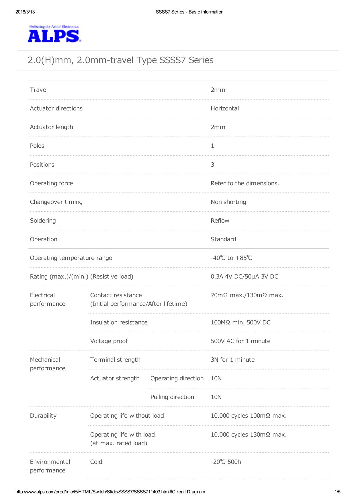
SSSS711403-ALPS.pdf
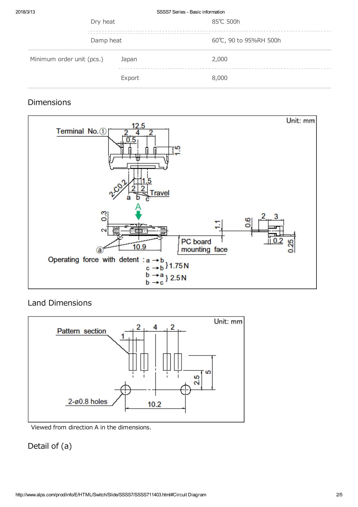
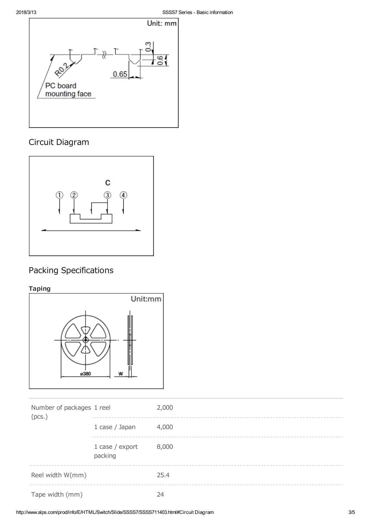
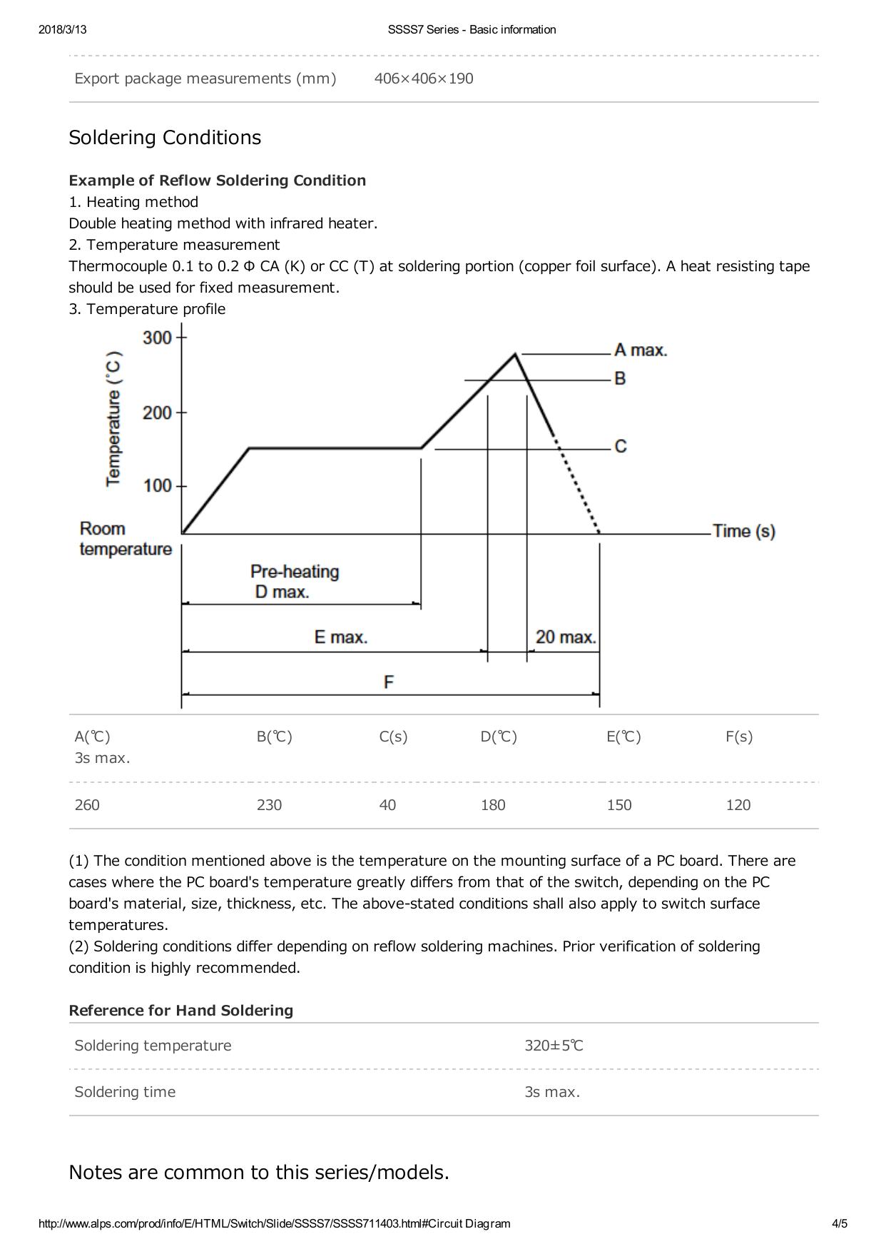
2018/3/13 SSSS7 Series - Basic information 2.0(H)mm, 2.0mm-travel Type SSSS7 Series Travel 2mm Actuator directions Horizontal Actuator length 2mm Poles 1 Positions 3 Operating force Refer to the dimensions. Changeover timing Non shorting Soldering Reflow Operation Standard Operating temperature range -40℃ to +85℃ Rating (max.)/(min.) (Resistive load) 0.3A 4V DC/50µA 3V DC Electrical performance Contact resistance (Initial performance/After lifetime) 70mΩ max./130mΩ max. Insulation resistance 100MΩ min. 500V DC Voltage proof 500V AC for 1 minute Terminal strength 3N for 1 minute Mechanical performance Actuator strength Durability Environmental performance Operating direction 10N Pulling direction 10N Operating life without load 10,000 cycles 100mΩ max. Operating life with load (at max. rated load) 10,000 cycles 130mΩ max. Cold -20℃ 500h http://www.alps.com/prod/info/E/HTML/Switch/Slide/SSSS7/SSSS711403.html#Circuit Diagram 1/5 2018/3/13 SSSS7 Series - Basic information Dry heat 85℃ 500h Damp heat 60℃, 90 to 95%RH 500h Minimum order unit (pcs.) Japan 2,000 Export 8,000 Dimensions Land Dimensions Viewed from direction A in the dimensions. Detail of (a) http://www.alps.com/prod/info/E/HTML/Switch/Slide/SSSS7/SSSS711403.html#Circuit Diagram 2/5 2018/3/13 SSSS7 Series - Basic information Circuit Diagram Packing Specifications Taping Number of packages 1 reel 2,000 (pcs.) 1 case / Japan 4,000 1 case / export packing 8,000 Reel width W(mm) 25.4 Tape width (mm) 24 http://www.alps.com/prod/info/E/HTML/Switch/Slide/SSSS7/SSSS711403.html#Circuit Diagram 3/5 2018/3/13 SSSS7 Series - Basic information Export package measurements (mm) 406×406×190 Soldering Conditions Example of Reflow Soldering Condition 1. Heating method Double heating method with infrared heater. 2. Temperature measurement Thermocouple 0.1 to 0.2 Φ CA (K) or CC (T) at soldering portion (copper foil surface). A heat resisting tape should be used for fixed measurement. 3. Temperature profile A(℃) B(℃) C(s) D(℃) E(℃) F(s) 230 40 180 150 120 3s max. 260 (1) The condition mentioned above is the temperature on the mounting surface of a PC board. There are cases where the PC board's temperature greatly differs from that of the switch, depending on the PC board's material, size, thickness, etc. The above-stated conditions shall also apply to switch surface temperatures. (2) Soldering conditions differ depending on reflow soldering machines. Prior verification of soldering condition is highly recommended. Reference for Hand Soldering Soldering temperature 320±5℃ Soldering time 3s max. Notes are common to this series/models. http://www.alps.com/prod/info/E/HTML/Switch/Slide/SSSS7/SSSS711403.html#Circuit Diagram 4/5 2018/3/13 SSSS7 Series - Basic information 1. This site catalog shows only outline specifications. When using the products, please obtain formal specifications for supply. 2. Please place purchase orders per minimum order unit (integer). 3. Products other than those listed in the above chart are also available. Please contact us for details. 4. Please contact us for automotive use products. http://www.alps.com/prod/info/E/HTML/Switch/Slide/SSSS7/SSSS711403.html#Circuit Diagram 5/5