 基恩士 FS-V11型光电传感器 说明书
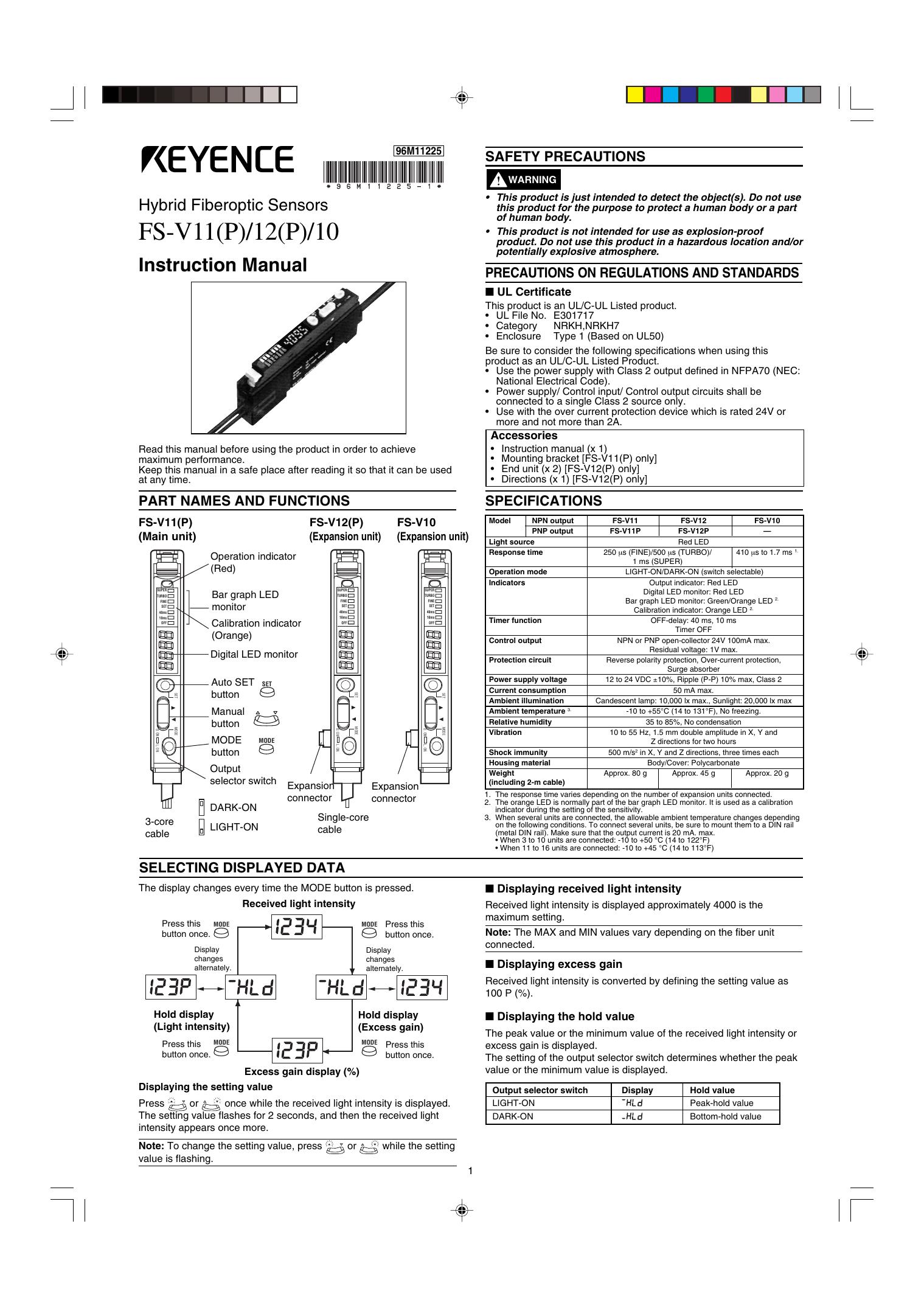
基恩士 FS-V11型光电传感器 说明书
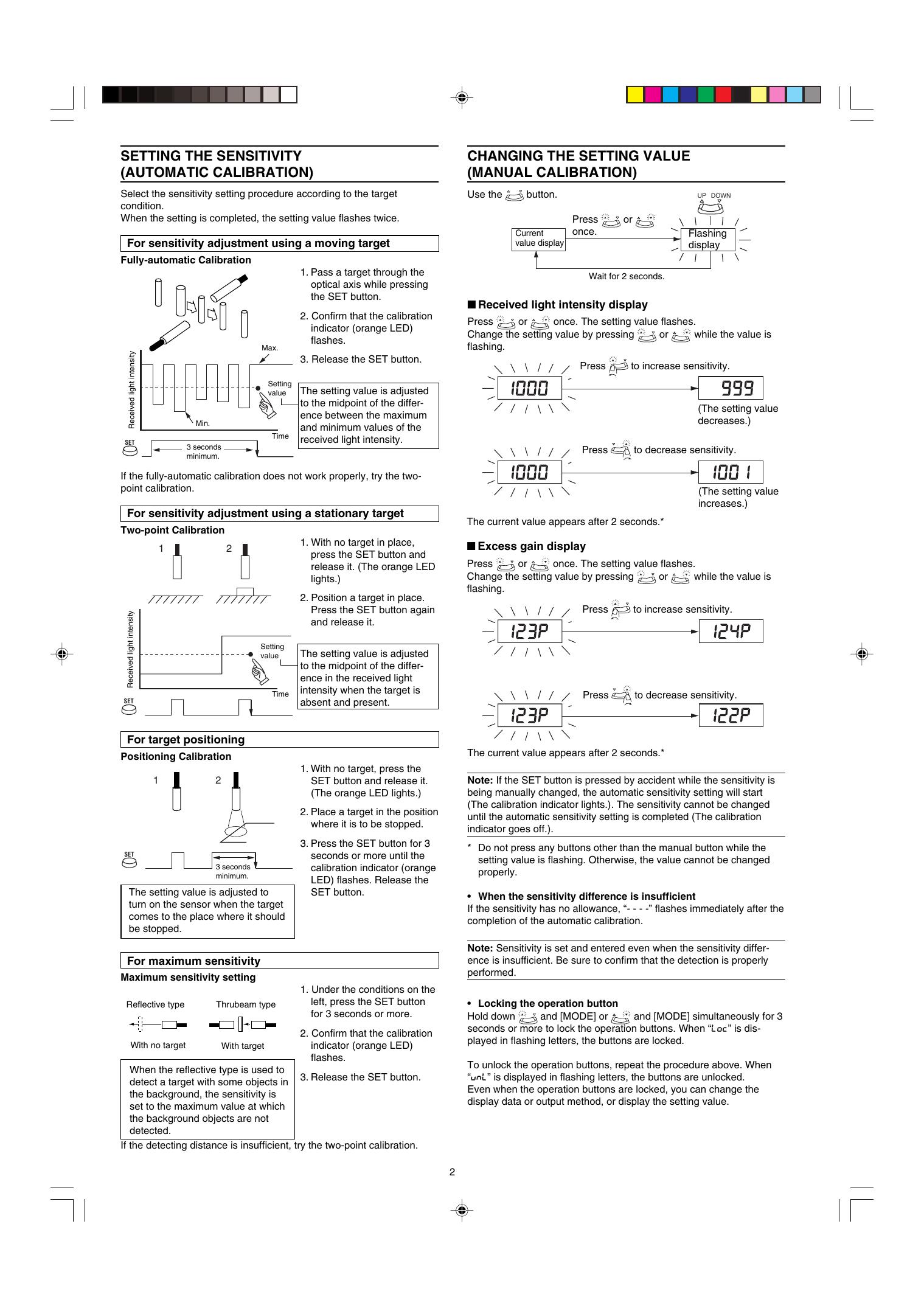
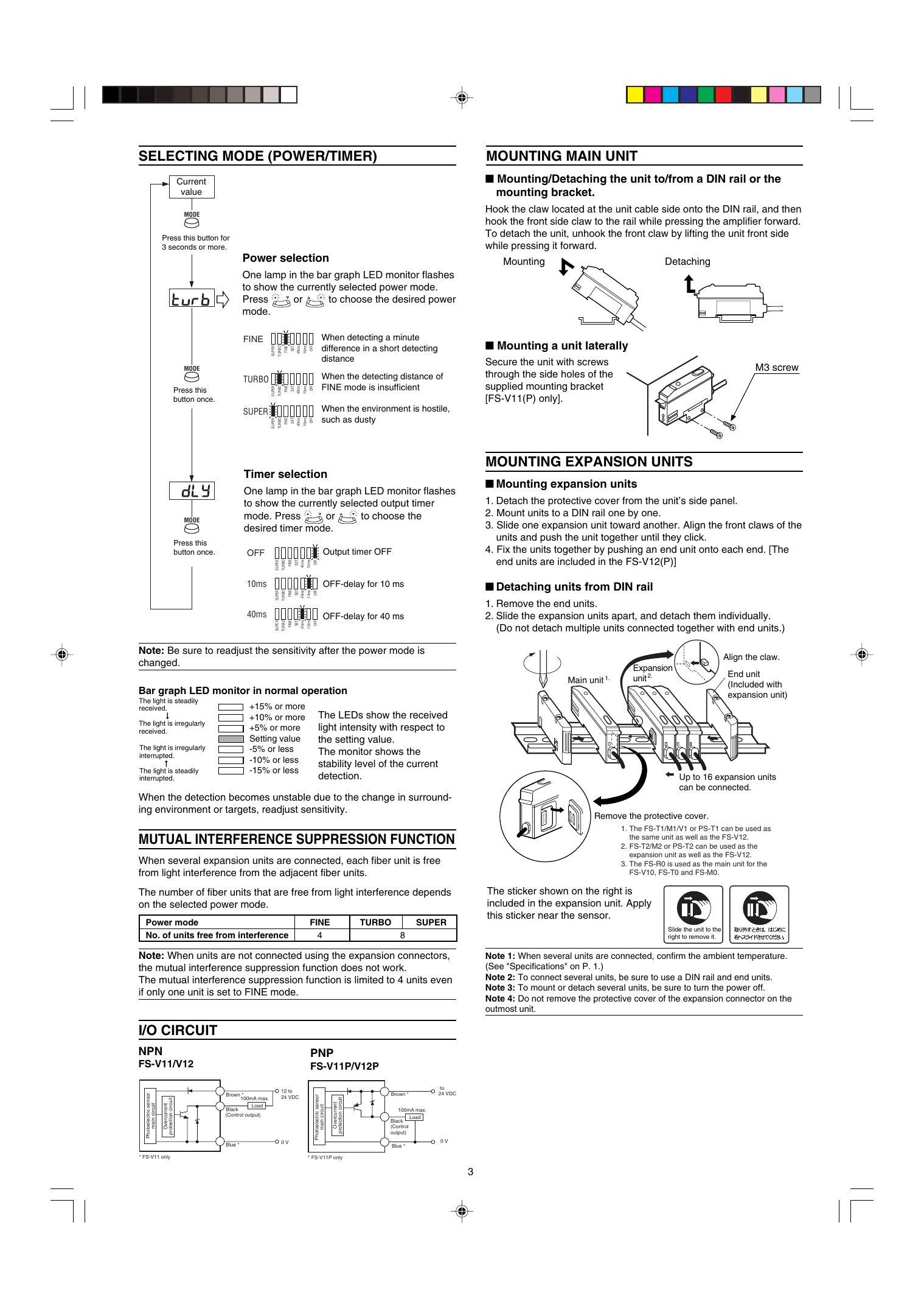
96M11225 SAFETY PRECAUTIONS WARNING • This product is just intended to detect the object(s). Do not use this product for the purpose to protect a human body or a part of human body. • This product is not intended for use as explosion-proof product. Do not use this product in a hazardous location and/or potentially explosive atmosphere. Hybrid Fiberoptic Sensors FS-V11(P)/12(P)/10 Instruction Manual PRECAUTIONS ON REGULATIONS AND STANDARDS ■ UL Certificate This product is an UL/C-UL Listed product. • UL File No. E301717 • Category NRKH,NRKH7 • Enclosure Type 1 (Based on UL50) Be sure to consider the following specifications when using this product as an UL/C-UL Listed Product. • Use the power supply with Class 2 output defined in NFPA70 (NEC: National Electrical Code). • Power supply/ Control input/ Control output circuits shall be connected to a single Class 2 source only. • Use with the over current protection device which is rated 24V or more and not more than 2A. Accessories • • • • Read this manual before using the product in order to achieve maximum performance. Keep this manual in a safe place after reading it so that it can be used at any time. PART NAMES AND FUNCTIONS SPECIFICATIONS FS-V12(P) (Expansion unit) FS-V11(P) (Main unit) FS-V10 (Expansion unit) Operation indicator (Red) SUPER TURBO FINE SET SUPER TURBO FINE SET SUPER TURBO FINE SET 40ms 10ms OFF 40ms 10ms OFF Calibration indicator (Orange) Control output Protection circuit SET SET SET L. ON L. ON L. ON Expansion connector Shock immunity Housing material Weight (including 2-m cable) Expansion connector DARK-ON LIGHT-ON MODE D. ON MODE D. ON MODE D. ON MODE Output selector switch 3-core cable Power supply voltage Current consumption Ambient illumination Ambient temperature 3. Relative humidity Vibration SET Manual button MODE button NPN output PNP output Light source Response time Timer function Digital LED monitor Auto SET button Model Operation mode Indicators Bar graph LED monitor 40ms 10ms OFF Instruction manual (x 1) Mounting bracket [FS-V11(P) only] End unit (x 2) [FS-V12(P) only] Directions (x 1) [FS-V12(P) only] FS-V11 FS-V11P FS-V12 FS-V10 FS-V12P — Red LED 250 µs (FINE)/500 µs (TURBO)/ 410 µs to 1.7 ms 1. 1 ms (SUPER) LIGHT-ON/DARK-ON (switch selectable) Output indicator: Red LED Digital LED monitor: Red LED Bar graph LED monitor: Green/Orange LED 2. Calibration indicator: Orange LED 2. OFF-delay: 40 ms, 10 ms Timer OFF NPN or PNP open-collector 24V 100mA max. Residual voltage: 1V max. Reverse polarity protection, Over-current protection, Surge absorber 12 to 24 VDC ±10%, Ripple (P-P) 10% max, Class 2 50 mA max. Candescent lamp: 10,000 lx max., Sunlight: 20,000 lx max -10 to +55°C (14 to 131°F), No freezing. 35 to 85%, No condensation 10 to 55 Hz, 1.5 mm double amplitude in X, Y and Z directions for two hours 500 m/s2 in X, Y and Z directions, three times each Body/Cover: Polycarbonate Approx. 80 g Approx. 45 g Approx. 20 g 1. The response time varies depending on the number of expansion units connected. 2. The orange LED is normally part of the bar graph LED monitor. It is used as a calibration indicator during the setting of the sensitivity. 3. When several units are connected, the allowable ambient temperature changes depending on the following conditions. To connect several units, be sure to mount them to a DIN rail (metal DIN rail). Make sure that the output current is 20 mA. max. • When 3 to 10 units are connected: -10 to +50 °C (14 to 122°F) • When 11 to 16 units are connected: -10 to +45 °C (14 to 113°F) Single-core cable SELECTING DISPLAYED DATA ■ Displaying received light intensity The display changes every time the MODE button is pressed. Received light intensity Press this button once. MODE MODE Display changes alternately. Received light intensity is displayed approximately 4000 is the maximum setting. Note: The MAX and MIN values vary depending on the fiber unit connected. Press this button once. Display changes alternately. ■ Displaying excess gain Received light intensity is converted by defining the setting value as 100 P (%). Hold display (Light intensity) Press this button once. ■ Displaying the hold value Hold display (Excess gain) MODE MODE The peak value or the minimum value of the received light intensity or excess gain is displayed. The setting of the output selector switch determines whether the peak value or the minimum value is displayed. Press this button once. Excess gain display (%) Displaying the setting value Output selector switch LIGHT-ON Press or once while the received light intensity is displayed. The setting value flashes for 2 seconds, and then the received light intensity appears once more. Note: To change the setting value, press value is flashing. or DARK-ON while the setting 1 Display Hold value Peak-hold value Bottom-hold value SETTING THE SENSITIVITY (AUTOMATIC CALIBRATION) CHANGING THE SETTING VALUE (MANUAL CALIBRATION) Select the sensitivity setting procedure according to the target condition. When the setting is completed, the setting value flashes twice. Use the button. UP DOWN Press or once. Current value display For sensitivity adjustment using a moving target Flashing display Fully-automatic Calibration 1. Pass a target through the optical axis while pressing the SET button. Received light intensity Max. Wait for 2 seconds. ■ Received light intensity display 2. Confirm that the calibration indicator (orange LED) flashes. Press or once. The setting value flashes. Change the setting value by pressing or while the value is flashing. 3. Release the SET button. Setting value Min. Time SET 3 seconds minimum. Press to increase sensitivity. The setting value is adjusted to the midpoint of the difference between the maximum and minimum values of the received light intensity. (The setting value decreases.) Press to decrease sensitivity. If the fully-automatic calibration does not work properly, try the twopoint calibration. (The setting value increases.) For sensitivity adjustment using a stationary target The current value appears after 2 seconds.* Two-point Calibration 1 1. With no target in place, press the SET button and release it. (The orange LED lights.) 2 ■ Excess gain display Press or once. The setting value flashes. or while the value is Change the setting value by pressing flashing. Received light intensity 2. Position a target in place. Press the SET button again and release it. Setting value Time SET The setting value is adjusted to the midpoint of the difference in the received light intensity when the target is absent and present. Press to increase sensitivity. Press to decrease sensitivity. For target positioning The current value appears after 2 seconds.* Positioning Calibration 1 1. With no target, press the SET button and release it. (The orange LED lights.) 2 Note: If the SET button is pressed by accident while the sensitivity is being manually changed, the automatic sensitivity setting will start (The calibration indicator lights.). The sensitivity cannot be changed until the automatic sensitivity setting is completed (The calibration indicator goes off.). 2. Place a target in the position where it is to be stopped. SET 3 seconds minimum. The setting value is adjusted to turn on the sensor when the target comes to the place where it should be stopped. 3. Press the SET button for 3 seconds or more until the calibration indicator (orange LED) flashes. Release the SET button. * Do not press any buttons other than the manual button while the setting value is flashing. Otherwise, the value cannot be changed properly. • When the sensitivity difference is insufficient If the sensitivity has no allowance, “- - - -” flashes immediately after the completion of the automatic calibration. Note: Sensitivity is set and entered even when the sensitivity difference is insufficient. Be sure to confirm that the detection is properly performed. For maximum sensitivity Maximum sensitivity setting Reflective type With no target Thrubeam type With target 1. Under the conditions on the left, press the SET button for 3 seconds or more. • Locking the operation button Hold down and [MODE] or and [MODE] simultaneously for 3 seconds or more to lock the operation buttons. When “Loc” is displayed in flashing letters, the buttons are locked. 2. Confirm that the calibration indicator (orange LED) flashes. To unlock the operation buttons, repeat the procedure above. When “vnL” is displayed in flashing letters, the buttons are unlocked. Even when the operation buttons are locked, you can change the display data or output method, or display the setting value. When the reflective type is used to detect a target with some objects in 3. Release the SET button. the background, the sensitivity is set to the maximum value at which the background objects are not detected. If the detecting distance is insufficient, try the two-point calibration. 2 SELECTING MODE (POWER/TIMER) MOUNTING MAIN UNIT ■ Mounting/Detaching the unit to/from a DIN rail or the mounting bracket. Current value Hook the claw located at the unit cable side onto the DIN rail, and then hook the front side claw to the rail while pressing the amplifier forward. To detach the unit, unhook the front claw by lifting the unit front side while pressing it forward. MODE Press this button for 3 seconds or more. Power selection Mounting Detaching One lamp in the bar graph LED monitor flashes to show the currently selected power mode. or to choose the desired power Press mode. When detecting a minute difference in a short detecting distance OFF SET 10ms FINE 40ms SUPER TURBO FINE ■ Mounting a unit laterally Secure the unit with screws through the side holes of the supplied mounting bracket [FS-V11(P) only]. OFF When the detecting distance of FINE mode is insufficient OFF MODE When the environment is hostile, such as dusty 10ms 40ms SET FINE SUPER Press this button once. TURBO TURBO 10ms 40ms SET FINE SUPER TURBO SUPER M3 screw MOUNTING EXPANSION UNITS Timer selection ■ Mounting expansion units One lamp in the bar graph LED monitor flashes to show the currently selected output timer or to choose the mode. Press desired timer mode. MODE Press this button once. 1. Detach the protective cover from the unit’s side panel. 2. Mount units to a DIN rail one by one. 3. Slide one expansion unit toward another. Align the front claws of the units and push the unit together until they click. 4. Fix the units together by pushing an end unit onto each end. [The end units are included in the FS-V12(P)] Output timer OFF OFF 10ms SET 40ms FINE SUPER TURBO OFF OFF 10ms SET 40ms FINE SUPER 40ms TURBO OFF-delay for 10 ms ■ Detaching units from DIN rail OFF-delay for 40 ms 1. Remove the end units. 2. Slide the expansion units apart, and detach them individually. (Do not detach multiple units connected together with end units.) OFF 10ms SET 40ms FINE SUPER TURBO 10ms Note: Be sure to readjust the sensitivity after the power mode is changed. Align the claw. Main unit 1. Expansion unit 2. End unit (Included with expansion unit) Bar graph LED monitor in normal operation The light is steadily received. ➞ +15% or more +10% or more +5% or more Setting value -5% or less -10% or less -15% or less The light is irregularly received. ➞ The light is irregularly interrupted. The light is steadily interrupted. The LEDs show the received light intensity with respect to the setting value. The monitor shows the stability level of the current detection. Up to 16 expansion units can be connected. When the detection becomes unstable due to the change in surrounding environment or targets, readjust sensitivity. Remove the protective cover. 1. The FS-T1/M1/V1 or PS-T1 can be used as the same unit as well as the FS-V12. 2. FS-T2/M2 or PS-T2 can be used as the expansion unit as well as the FS-V12. 3. The FS-R0 is used as the main unit for the FS-V10, FS-T0 and FS-M0. MUTUAL INTERFERENCE SUPPRESSION FUNCTION When several expansion units are connected, each fiber unit is free from light interference from the adjacent fiber units. The sticker shown on the right is included in the expansion unit. Apply this sticker near the sensor. The number of fiber units that are free from light interference depends on the selected power mode. Power mode No. of units free from interference FINE 4 TURBO SUPER Slide the unit to the right to remove it. 8 Note: When units are not connected using the expansion connectors, the mutual interference suppression function does not work. The mutual interference suppression function is limited to 4 units even if only one unit is set to FINE mode. Note 1: When several units are connected, confirm the ambient temperature. (See "Specifications" on P. 1.) Note 2: To connect several units, be sure to use a DIN rail and end units. Note 3: To mount or detach several units, be sure to turn the power off. Note 4: Do not remove the protective cover of the expansion connector on the outmost unit. I/O CIRCUIT Blue * * FS-V11 only 12 to 24 VDC Overcurrent protection circuit Brown * 100mA max. Load Black (Control output) Photoelectric sensor main circuit FS-V11P/V12P Overcurrent protection circuit PNP FS-V11/V12 Photoelectric sensor main circuit NPN 0V Brown * to 24 VDC 100mA max. Load Black (Control output) 0V Blue * * FS-V11P only 3 CONNECTING FIBER UNIT • The required adaptor is included in each model of the FU series. If an inadequate adaptor is used, the fiber unit cannot be properly installed. Lower the quick-release lever, insert the fiber unit about 14 mm until it reaches the end, and then lift the quick-release lever. 1 2 Cable outer dia. ø1.3 Fiber insertion mark ø1.0 Adapter Adapter A (OP-26500) Adapter B (OP-26501) Appearance • To connect a fiber unit with a small diameter, use the adaptor included with the FU series. 1 1. Attach the adaptor to the fiber unit. 2. Fully insert the adaptor into the mounting holes of the amplifier, and then lift the quick-release lever. • To connect the coaxial reflective type fiber unit to the amplifier, connect the single-core fiber to the transmitter side, and connect the multiple-core fiber to the receiver side. (Connect the fibers according to the marking on the amplifier lateral side.) 2 2 Transmitter Receiver Multiple-core Note: If the fiber unit is improperly connected, the sensor cannot meet the specifications. DIMENSIONS HINTS ON CORRECT USE Unit: mm When the mounting bracket [included in FS-V11(P)] is attached: FS-V11(P) *ø3.9 3-core x Brown/Blue/Black: 0.34 mm2 Cable length: 2 m 0.7 • To extend the cable length, use a cable with at least a 0.3 mm2 cross-section area. Limit the length of cable extension to no more than 100 m. (To connect several units, contact Keyence for further information.) 3 9 36.5 (Maximum when the cover is opened) 90 DIN-rail mounting 0.7 3.8 8 3 • If the amplifier cable is placed together with power lines or high voltage lines in the same conduit, detection error may occur due to noise interference, or the sensor may be damaged. Isolate the amplifier cable from these lines. 16 22.8 12 min. 2 x ø3.4 Spot facing: ø6, 2.7 (d) 4 25.6 (33) 28.5 25.4 30.8 (13) 2 x (4.4 x 3.4) Spot facing: ø7, 4 (d) 6.7 20.7 35.4 • When using a commercially available switching regulator, ground the frame ground terminal and ground terminal. 9 12 min. 66 15 31 FS-V12(P) ø2.6 single-core x 0.34 mm2 Cable length: 2 m End unit [included in FS-V12(P)] 9 6 (Maximum when the cover is opened) 90 4 DIN-rail mounting 0.7 3 DIN-rail mounting (33)28.5 (22.6) 20.8 Single-core • Do not use the FS series outdoors, or in a place where extraneous light can enter the light receiving surface directly. • Due to the individual dispersion of characteristics and the difference in fiber unit model, the maximum sensing distance or displayed value of all the units are not the same. (13) 6.7 20.7 35.4 11 min. 66 35.4 9.2 53.8 FS-V10 • Improper wiring may cause the amplifier to become hot or may change the sensitivity. • The displayed value may vary depending on the surrounding environment (change in temperature, dust, etc.). 9 (Maximum when the cover is opened) 90 4 DIN-rail mounting 0.7 WARRANTIES (MUST ACCOMPANY THE PRODUCTS): KEYENCE, at its sole option, will refund, repair or replace at no charge any defective Products within 1year from the date of shipment. Unless stated otherwise herein, the Products should not be used internally in humans, for human transportation, as safety devices or fail-safe systems. EXCEPT FOR THE FOREGOING, ALL EXPRESS, IMPLIED, AND STATUTORY WARRANTIES, INCLUDING WARRANTIES OF MERCHANTABILITY, FITNESS FOR A PARTICULAR PURPOSE AND NON-INFRINGEMENT OF PROPRIETARY RIGHTS, ARE EXPRESSLY DISCLAIMED. KEYENCE SHALL NOT BE LIABLE FOR ANY DIRECT, INDIRECT, INCIDENTAL, CONSEQUENTIAL OR OTHER DAMAGES, EVEN IF DAMAGES RESULT FROM THE USE OF THE PRODUCTS IN ACCORDANCE WITH ANY SUGGESTIONS OR INFORMATION PROVIDED BY KEYENCE. In some jurisdictions, some of the foregoing warranty disclaimers or damage limitations may not apply. 3 (33)28.5 6.7 20.7 35.4 66 When several units are connected: No. of units End unit1. End unit1. 6 L 6 1 2 3 4 5 6 7 8 9 10 11 12 13 14 15 16 17 L 9 18 27 36 45 54 63 72 81 90 99 108 117 126 135 144 153 KEYENCE CORPORATION 1-3-14, Higashi-Nakajima, Higashi-Yodogawa-ku, Osaka, 533-8555, Japan PHONE: +81-6-6379-2211 Specifications are subject to change without notice. Copyright (c) 2010 KEYENCE CORPORATION. All rights reserved. Note: Be sure to use the end units to connect to the expansion units. 11225E 1080-1 96M11225 Printed in Japan 4 A7WW1-MAN-0069